


Blog
Is the plug-in flow meter easy to use?
When it comes to flowmeter, what do you think of? The first one must be the turbine flowmeter, which is the most common and widely used in the hydraulic industry.

This flow meter is a tubular flow design, and the oil can completely pass through the metering channel of the flow meter. There is a turbine blade element inside the flow meter channel. When the oil flows through, it will drive the turbine blade inside the flow meter to rotate. The sensor counts once for each rotation of the turbine. The faster the fluid flows, the faster the blade rotates. The speed and number of revolutions of the blade reflect the flow of the oil.

In terms of signals, the turbine flowmeter first converts the flow rate of the oil into the rotation speed of the turbine blades and then converts the rotation speed into an electrical signal proportional to the flow rate. This flowmeter is used to detect instantaneous flow and total flow, and the frequency as its output signal makes it very easy to digitize. When the ferromagnetic turbine blades pass through the magnet, the magnetic resistance of the magnetic circuit changes, thereby generating an induction signal. The signal is amplified and shaped by the amplifier, and after being sent to the counter or frequency meter, the flow rate is displayed. At the same time, the pulse frequency is converted from frequency to voltage to indicate the instantaneous flow rate. The speed of the impeller is proportional to the flow rate, and the number of revolutions of the impeller is proportional to the total amount of flow.

The turbine flowmeter is equipped with sensors arranged vertically with the impeller, with the temperature (pressure) sensor on the left, the flow sensor in the middle, and the pressure sensor on the right. This layout makes it easier for the sensor to sense the magnetism of the ferromagnetic blades. However, it also makes the entire sensor relatively large in height.

There are internal threads at both ends of the sensor, which can be connected to the hydraulic system with connectors with external threads at both ends. However, it is a little complicated that two conversion connectors with suitable threads must be prepared each time. In addition, because a flow meter is to be added, a straight hydraulic pipeline on the original equipment needs to be removed and replaced with a “flow meter in the middle, a hydraulic pipe at each end”, so each piping takes a lot of time and effort. If you are servicing a non-standard device, then in most cases these pipes can only be used once, and they are useless after measuring the flow.

Dale Dietel of DGD Company in the United States invented a new flow meter – a cartridge flow meter. Dale named it CFT (Cartridge Flow Transmitter). This CFT design is the first in the industry. It makes the flow meter a cartridge structure, and its size design is designed to fully match the T-18A hole of Sun, making it more convenient and flexible to use. The actual object looks like the following and is close to the size of an ordinary cartridge valve.
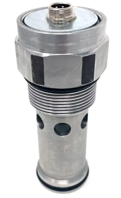

Let’s take a look at how it works through the internal structure diagram of the plug-in flowmeter below.
In response to the problem that the turbine flowmeter places the sensing part of the sensor perpendicular to the turbine, which causes excessive height, the plug-in flowmeter designs the turbine inside the plug-in valve. After all the oil flows through the turbine blades, it flows out from the valve hole. Although the principle is similar, CFT uses a Hall effect sensor from the top (green part) to monitor the speed by sensing the magnet in the turbine hub. In this way, there is no need to make the blades magnetic, nor to sense the blade signals. It only needs to sense the rotation of the dedicated magnet element on the top.

Another feature of this flow meter is that the same flow meter can achieve 16 flow range settings (minimum 38L, maximum 475L) by simply selecting the corresponding dip switch on the circuit board. This solves the problem of balancing the large flow demand for accurate measurement.
(1) It saves a lot of space in terms of height and length, and the overall volume is reduced. In addition, it also saves the seals at several sensors.
(2) This plug-in flowmeter can be directly installed on the valve block. In the future, if it is on the valve block, the flow can be measured, and if it is not, it cannot be tested. It is a one-time deal, and there is no need to consider piping. Compared with the turbine flowmeter, this point can only be said to have its own advantages.
(3) The flow range can be adjusted in a very creative way. It can accurately measure small flow conditions such as startup and micro-motion and can also take care of the daily needs of large flow.
(4) From the figure, the components in this new design structure are much simpler than those of the turbine flowmeter. If it is mass-produced, the cost should be reduced.


These functions alone are not enough. DGD continues to work hard. In November 2024, it announced the launch of the latest product of its plug-in flow sensor production line: CFT-Max. The flow rate of this CFT-Max product can reach 580L, the pressure level is 415bar, and it can meet the J1939 communication standard. This makes it easy to input the information of the flow meter into the main control system of the machine. So that the system can make a judgment. Since this plug-in flow meter needs to reserve a plug-in hole on the circuit of the valve block when the equipment leaves the factory before it can be integrated into the valve block, the function of the hydraulic system and the design of the valve block must be planned in advance, and it is also more suitable for large-scale use.

DGD also targets mobile machinery, and they advertise that this flow meter is “designed for mobile hydraulic systems”. The production cycle of this product is about 2 to 3 weeks on foreign websites. However, its current retail price is not low. A sales company gave a specific value of about US$1,500 per CFT-Max. This price is still a bit high if it is used for construction machinery, at least for domestic construction machinery manufacturers, it is still difficult to accept. However, based on its internal structure and parts are not complicated, the price is expected to drop in the future if it is mass-produced.

The following is the test result display curve of 25GPM (0~95L) and 100GPM (0~380L) flowmeter, the ordinate is the actual flow rate, and the abscissa is the current output. The red curve in the two curves is the actual flow rate displayed by the standard flowmeter used for testing, and the blue curve is the current curve output by the CFT flowmeter. It seems that the measurement accuracy is still good.


